• MARINE VALVE 0117
    HVG MARINE VALVE 0117

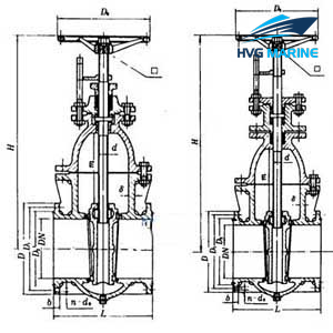
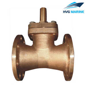
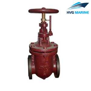
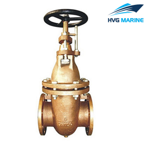
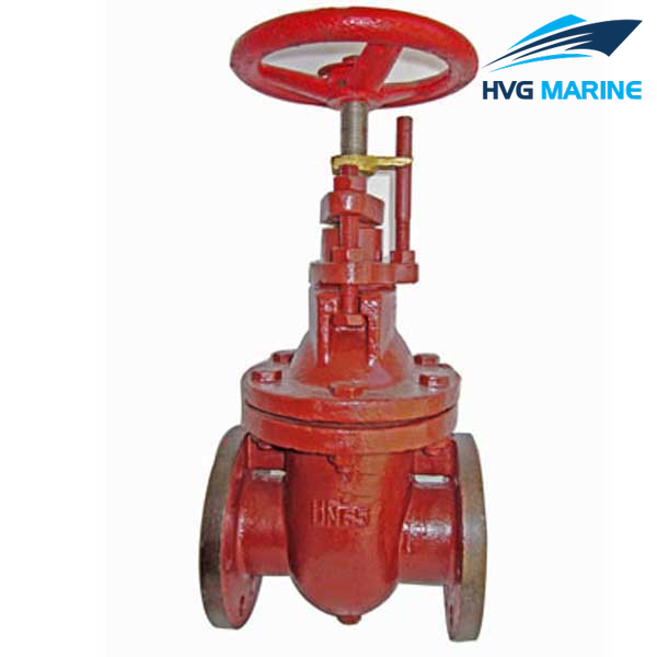
    HVG MARINE VALVE 0117: Marine Cast Iron Gate valve GB/T465-1995

    1.Design standard:CBT465-1995.

    2.End standard:GB/T2501&GB/T569.

    3.End type:Flange.

    4.PN:0.25/0.4/0.6Mpa.

    5.DN:50mm-500mm.

    6.Main material:

    • Body/Bonnet:HT200;
    • Seat:SS410/BC6;
    • Stem:SS410/BS;
    • Disc:SS410/BC6.

    7.Application:Sea water piping,fresh water piping and oil piping.

    8.Function:Such valves are used for on-off duty.

    Drawing of Marine Cast Iron Gate valve GB/T465-1995:


    Technical specification:

    • Fundamental dimensions of Marine Cast Iron Gate valve GB/T465-1995:

    Chart 1 Fundamental dimensions of type A:

    PN

    DN

    Structure dimension

    Flange

    Bolt

    Stem

    Hand

    wheel

    Lift

    range

    m

    Weight

    kg

    Mpa

    mm

    L/mm

    H /mm

    D/mm

    D1/mm

    D2/mm

    b/mm

    d0/mm

    n

    Th.

    d/mm

    口/mm

    D0/mm

    0.6

    50

    190

    340

    135

    103

    84

    16

    15

    6

    M14

    Tr20x8(P4)LH

    14

    180

    60

    20

    65

    200

    372

    155

    123

    104

    15

    15

    6

    M14

    Tr20x8(P4)LH

    14

    180

    75

    24

    80

    220

    430

    170

    138

    118

    15

    15

    8

    M14

    Tr24x10(P5)LH

    17

    200

    92

    33

    100

    220

    460

    190

    158

    138

    15

    15

    8

    M14

    Tr24x10(P5)LH

    17

    200

    112

    40

    125

    242

    528

    215

    183

    164

    15

    15

    10

    M14

    Tr26x10(P5)LH

    19

    225

    138

    61

    150

    248

    566

    240

    208

    190

    16

    15

    12

    M14

    Tr26x10(P5)LH

    19

    225

    165

    70

    0.4

    175

    268

    630

    270

    238

    221

    16

    15

    12

    M14

    Tr28x10(P5)LH

    22

    250

    190

    85

    200

    278

    685

    295

    264

    247

    16

    15

    12

    M14

    Tr28x10(P5)LH

    22

    250

    215

    100

    250

    310

    755

    365

    327

    306

    18

    17

    14

    M16

    Tr30x10(P5)LH

    24

    280

    265

    153

    300

    345

    835

    430

    385

    360

    19

    21

    14

    M20

    Tr30x10(P5)LH

    24

    280

    315

    199

    Chart 2 Fundamental dimensions of type AS:

    PN

    Mpa

    DN

    mm

    Structure

    dimension

    Flange

    Bolt

    Stem

    Hand

    wheel

    Lift

    range

    m

    Weight

    kg

    L/mm

    H/mm

    D/mm

    D1/mm

    D2/mm

    b/mm

    d0/mm

    n

    Th.

    d/mm

    口/mm

    D0 /mm

    0.6

    50

    178

    340

    140

    110

    90

    16

    14

    4

    M12

    Tr20x8(P4)LH

    14

    180

    60

    20.3

    65

    190

    372

    160

    130

    110

    16

    14

    4

    M12

    Tr20x8(P4)LH

    14

    180

    75

    24.5

    80

    203

    430

    190

    150

    128

    18

    18

    4

    M16

    Tr24x10(P5)LH

    17

    200

    92

    33.8

    100

    229

    460

    210

    170

    148

    18

    18

    4

    M16

    Tr24x10(P5)LH

    17

    200

    112

    41.2

    125

    254

    528

    240

    200

    178

    20

    18

    8

    M16

    Tr26x10(P5)LH

    19

    225

    138

    62.1

    150

    267

    566

    265

    225

    202

    20

    18

    8

    M16

    Tr26x10(P5)LH

    19

    225

    165

    71.6

    0.4

    175

    292

    630

    295

    255

    232

    22

    18

    8

    M16

    Tr28x10(P5)LH

    22

    250

    190

    86.4

    200

    292

    685

    320

    280

    258

    22

    18

    8

    M16

    Tr28x10(P5)LH

    22

    250

    215

    101.8

    250

    330

    755

    375

    335

    312

    24

    18

    12

    M16

    Tr30x12(P6)LH

    24

    280

    265

    155.1

    300

    356

    835

    440

    395

    365

    24

    22

    12

    M20

    Tr30x12(P6)LH

    24

    280

    315

    201.2

    0.25

    350

    381

    1050

    490

    445

    415

    26

    22

    12

    M20

    Tr36x12(P6)LH

    27

    320

    365

    298.3

    400

    406

    1145

    540

    495

    465

    28

    22

    16

    M20

    Tr36x12(P6)LH

    27

    360

    418

    372.1

    450

    432

    1330

    595

    550

    520

    28

    22

    16

    M20

    Tr40x12(P6)LH

    32

    400

    468

    560.0

    500

    457

    1420

    645

    600

    570

    30

    22

    20

    M20

    Tr40x12(P6)LH

    32

    450

    518

    627.4