• VENTILATION EQUIPMENT 0050 VENTILATION EQUIPMENT 0050 VENTILATION EQUIPMENT 0050
    HVG MARINE VENTILATION EQUIPMENT 0050

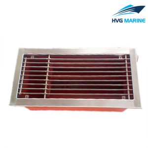
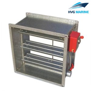
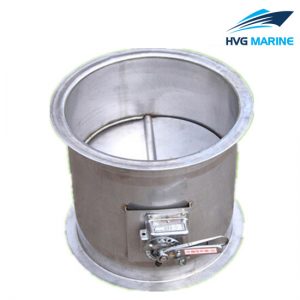
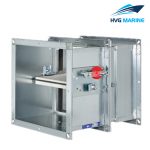
    HVG MARINE VENTILATION EQUIPMENT 0050: Aluminum Fire Damper

    Specification:

    In case of a fire,fire dampers shut automatically to prevent the propagation of fire and smoke through ductwork to adjacent designated fire compartments,The fire dampers are tested,Local requirements and building inspectorate approvals are essential in the countyr where the units are to be installed.

    Correct approved installation locations are in solid walls and ceiling slabs,on the face of solid walls,adjacent to and remote from solid walls,upright on solid ceiling slabs,in lightweight partition walls,in lightweight fire walls,and in shaft walls,Installation in horizontal and vertical ducts,Airflow direction is not critical,When installed in walls or ceiling slabs combustible ventilation ducting may be connected directly to the fire damper,In the case of fire,the damper is triggered at 72℃ or 95℃(for use in warm air ventilation system)either by a fusible link or thermoelectrically with a spring return,The fire dampers have two inspection accesses.

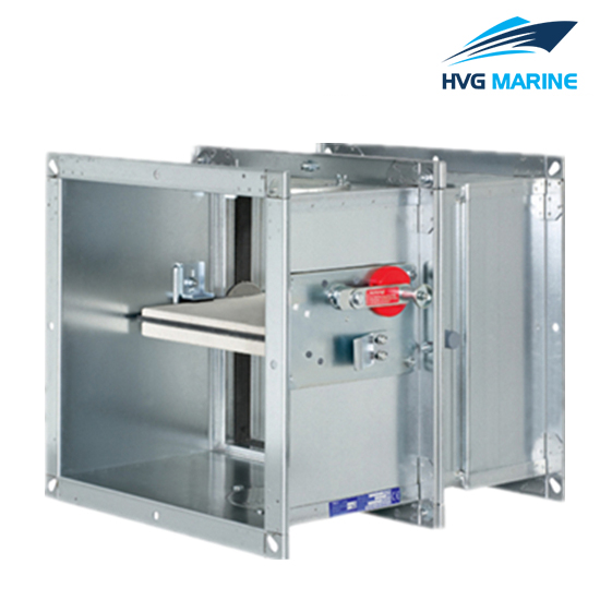
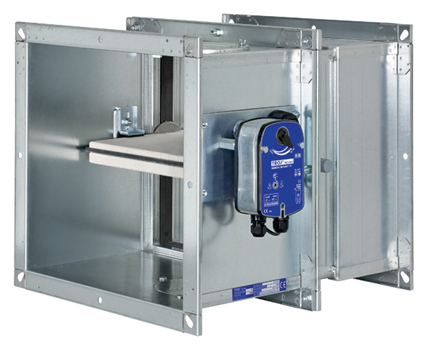
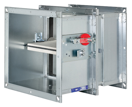
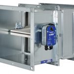
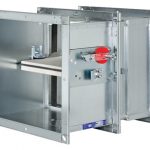
    Aluminum Fire Damper Features:

    • Retangular fire damper
    • complies with the European product standard DIN EN 15650
    • EG-Certificate of conformity
    • BC1-606-4645-15650.11-4651
    • Tested for fire resistance properties according to EN 1366-2
    • Classification according to EN 1350-3
    • Reduced diffrential pressure and sound power level
    • Dry mortarless installation with installation kit
    • Remote controlled with spring return actuator

    Technical specification:

    • Aluminum Fire Damper Dimension:

    Range

    Type

    Construction details

    Sealing

    Classification

    200X200
    up to
    1500X800
    (mm)

    Rigid floor

    Aerated concrete
    min.125mm,p>600kg/m3
    reduced casing distance100mm
    reduced distance to supporting
    construction≥40mm

    In the floor
    with mortar
    (wet mounting)

    EI90(h。i ↔o)
    S-(300Pa)

    Rigid wall Aerated concrete
    min.100mm,p>500kg/m3
    reduced casing distance70mm

    In the floor
    with mortar
    (wet mounting)

    EI90(Ve i ↔o)
    S-(300Pa)

    Aerated concrete
    min.100mm,p>500kg/m3
    reduced distance to supporting
    construction≥40mm

    In the floor
    with mortar &
    Partial mineral
    wool

    EI90(Ve i ↔o)
    S-(300Pa)

    Aerated concrete
    min.100mm,p>500kg/m3

    In the floor
    with mortar
    (dry mounting)

    EI90(Ve i ↔o)
    S-(300Pa)


    Aerated concrete
    min.100mm,
    p>500kg/m3

    Casing

    Protection
    with
    Promated H/
    Promated
    LS35
    and mineral wool

    Onto the wall
    installation kit
    (dry mounting)

    EI90(Ve i ↔o)
    S-(300Pa)

    Casing&
    ducting

    Remote to a
    distance of 260mm from wall installation
    kit(dry mounting)

    EI90(Ve i ↔o)
    S-(300Pa)

    Remote from wall installation
    kit(dry mounting)

    EI90(Ve i ↔o)
    S-(300Pa)