• MARINE ANODE 0012
    HVG MARINE ANODE 0012

    HVG MARINE ANODE 0012: Aluminum Anode

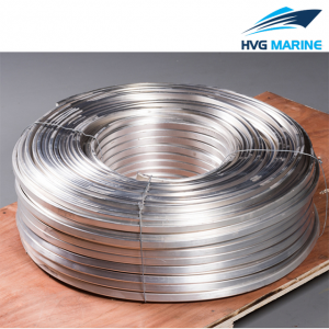
    Aluminum zinc indium system (AZI) sacrificial anode is casted by high purity aluminum, zinc, indium and other metal alloy. Aluminum alloy anode is produced in line with the implementation of GB4948-2002 Aluminum Zinc Indium Alloy Sacrificial Anode.

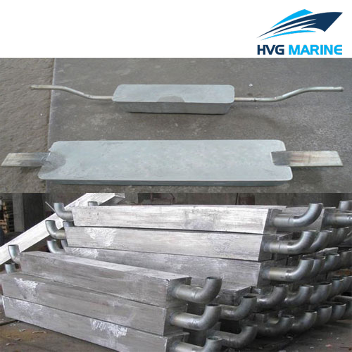
    The aluminum anode can prevent the corrosion of steel structure in seawater, widely used for the anti-corrosion of the ship hull, pressurized water tank, seawater pipeline, port and terminal facilities, marine engineering, drilling platform, condensator and pipelines in soil. The performance of aluminum anode is influenced by the chemical composition of the alloy, so we offer different composition of aluminum alloys to meet our customer requirements.

    Main Performance: The driving voltage is low; light weight; high current efficiency.
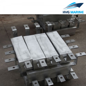
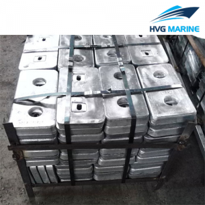
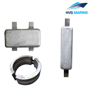
    Product Categories:

    • Ordinary Aluminum Alloy Sacrificial Anode;
    • Highly Activated Aluminum Alloy Sacrificial Anode;
    • High Efficiency Aluminum Alloy Sacrificial Anode;
    • High Temperature Aluminum Alloy Sacrificial Anode;
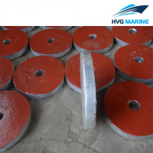
    • Bracelet Type Aluminum Alloy Sacrificial Anode.

    Note: our company can also design and produce all kinds of special specifications and properties of aluminum alloy sacrificial anode according to the different needs of customers.

    Technical specification:

    • Chemical Composition
    • Electrochemical Properties
    • Aluminum Anode for Ship Hull
    • Aluminum Anode for Ballast Water Tank
    • Aluminum Anode for Harbor and Marine Engineering Facilities
    • Aluminum Anode for Storage Tank
    • Aluminum Anode for Seawater Cooling System
    • Aluminum Anode for Buried Pipeline
    • Bracelet Type Aluminum Anode
    Alloy Type Zn In Cd Sn Mg Si Ti Impurity, ≤ Al
    Si Fe Cu
    Al-Zn-In-Sd 2.5-4.5 0.018-0.050 0.005-0.020 0.10 0.15 0.01 margin
    Al-Zn-In-Sn 2.2-5.2 0.020-0.045 0.018-0.035 0.10 0.15 0.01 margin
    Al-Zn-In-Si 5.7-7.0 0.025-0.035 0.10-0.15 0.10 0.0-15 0.01 margin
    Al-Zn-In-Sn-Mg 2.5-4.0 0.020-0.050 0.025-0.075 0.50-1.00 0.10 0.15 0.01 margin
    Al-Zn-In-Mg-Ti 4.0-7.0 0.020-0.050 0.50-1.50 0.01-0.08 0.10 0.15 0.01 margin


    Type/Index/Performance Open Circuit Potential-V(SCE) Working Potential-V(SCE) Actual Capacitance(A.h/kg) Current Efficiency% Dissolution Status
    Ordinary Aluminum Alloy Sacrificial Anode 1.10-1.18 1.05-1.12 ≥2400 ≥85 Corrosion products are easy to fall off, the surface dissolution is even
    High Efficiency Aluminum Alloy Sacrificial Anode 1.10-1.18 1.05-1.15-2 ≥2600 ≥90
    Highly Activated Aluminum Alloy Sacrificial Anode 1.45-1.50 1.40-1.45 ≥2080 ≥70
    Type Specification mm Weight kg
    A×B×C
    AH-1 800×140×60 17.0
    AH-2 800×140×50 15.0
    AH-3 800×140×40 12.0
    AH-4 600×120×50 10.0
    AH-5 400×120×50 6.5
    AH-6 500×100×40 5.5
    AH-7 400×100×40 4.5
    AH-8 300×100×40 3.5
    AH-9 250×100×40 2.5
    AH-10 180×70×35 1.2
    AH-11 300×150×50 Double Iron Feet 5.8
    AH-12 300×150×40 Double Iron Feet 4.6
    AH-13 300×150×50 Bolt Type 5.8
    AH-14 300×150×40 Bolt Type 4.8
    Type Specification mm Weight kg
    A×(B1+B2)×C
    AT-1 500×(115+135)×130 23.0
    AT-2 1500×(65+75)×70 21.5
    AT-3 500×(110+130)×120 20.0
    AT-4 1000×(58.5+78.5)×68 13.2
    AT-5 800×(56+74)×65 10.0
    AT-9 1150×(48+54)×51 9.0
    AT-7 250×(80+100)×85 5.0
    AT-8 200×(70+90)×70 3.0
    Type Specification mm Weight kg
    A×(B1+B2)×C
    AI-1 2300×(220+240)×230 310.0
    AI-2 1600×(200+210)×220 190.0
    AI-3 1500×(170+200)×180 130.0
    AI-4 900×(150+170)×160 58.0
    AI-5 1500×(148+178)×170 120.0
    AI-6 850×(180+220)×180 85.0
    AI-7 800×(200+280)×150 60.0
    AI-8 700×(160+220)×180 72.5
    AI-9 1250×(115+135)×130 56.0
    AI-10 1000×(115+135)×130 46.0
    AI-11 750×(115+135)×130 35.0
    AI-12 500×(115+135)×130 23.0
    Type Specification/mm Weight (kg)
    A×(B1+B2)×C
    AC-1 750×(115+135)×130 35.0
    AC-2 500×(115+135)×130 23.0
    AC-3 500×(105+135)×100 16.0
    AC-4 300×(105+135)×100 10.0
    Type Specification mm Weight kg
    A×(B1+B2)×C
    AE-1 1200×(200+280)×150 120.0
    AE-2 800×(200+280)×150 80.0
    AE-3 1000×(115+135)×130 46.0
    AE-4 500×(115+135)×130 23.0
    AE-5 1000×(80+100)×80 20.0
    AE-6 500×(105+135)×100 16.0
    AE-7 500×(80+100)×80 10.0
    AE-8 400×(110+120)×50 7.0
    AE-9 300×(140+160)×40 5.0
    AE-10 200×(90+110)×40 3.0
    AE-11 300×50 Disc Shape 11.5
    AE-12 360×40 Disc Shape 9.0
    AE-13 300×40 Disc Shape 7.5
    AE-14 200×50 Disc Shape 4.0
    AE-15 180×50 Disc Shape 3.5
    AE-16 120×100 Disc Shape 2.5
    Type Specification mm Iron Feet Size mm Weight kg
    A×2B×C×D E F H
    AP-5 420×622×51×20 480 4 6 AP-5
    AP-6 254×559×76×25 284 4 6 AP-6
    AP-7 400×503×51×25 430 4 6 AP-7
    AP-8 562×371×51×25 592 4 6 AP-8
    Specification: Inside Diameter*Width*Thickness* Interval

    mm

    Weight

    kg/pair

    Iron Core Specification

    mm

    Φ1020×200×35×51 68 5×50
    Φ819×60×30×51 13 5×25
    Φ624×80×30×51 17 5×50
    Φ513×100×30×51 17 5×50
    Φ487×200×45×51 41 5×50
    Φ470×480×25×51 50 5×50
    Φ436×480×38×51 70 5×50
    Φ420×413×45×51 69 5×50
    Φ385×150×59×51 32 5×50
    Φ335×505×38×51 56 5×50
    Φ280×250×45×51 29 5×50
    Φ252×250×45×51 26 5×50