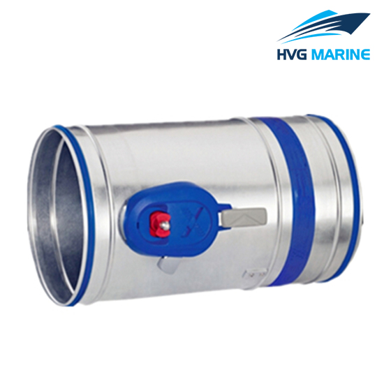

HVG MARINE VENTILATION EQUIPMENT 0054: Marine Circular Fire Damper
Application :
- The class of perforemance of the circular fire damper depends on the application.
- Installation in solid walls and ceilling slabs whose class of performance is lower than that of the fire damper is approved.
- In this case the class of performance of the wall or ceiling slab applies also to the type of circular fire damper.
- The fire damper is approved only for use in ventilation systems.Ducts must be connected on both ends,or a duct on one end and a cover grille on the other end.
- Installation of fire dampers must be carried out in compliance with provision of federal state law and generally recongnized codes of practice.
- Ducting must be installed in such a manner that it does not imposed any loads on the fire damper in case of a fire.
- For information on how to limit such a manner please refer to the guidline regarding fire protection requirements on vetilation systems.
- It is recommanded to use flexible connectors to connect rigid ducting to the fire damper for particular applications.
- Flexible ducting may be connected directly to the fire damper.
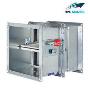
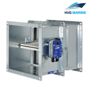
Features:
- Casing in galvanised sheet steel or in stainless steel.
- Damper blade made of special insulation material.
- Damper blade steal made of neoprence.
- Air flow in either directions.
- Large free cross sectional area,hence low diffrencial pressure
- Release temperature 72℃ or 95℃(for use in warm air ventilation systems).
- Approved installation orientation from 0° to 360°.
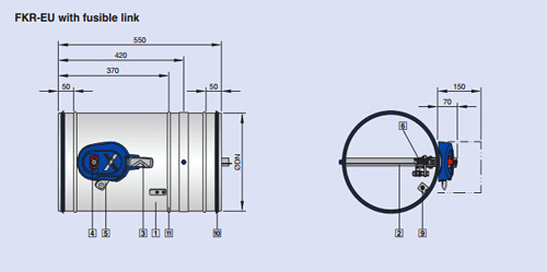
Drawing: