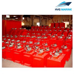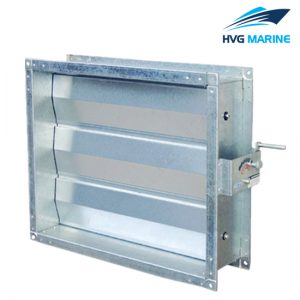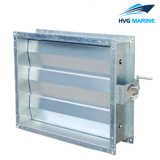
HVG MARINE VENTILATION EQUIPMENT 0041: Galvanized Electrical Fire Damper
Applications :
- Fire dampers are used in marine or bulidings to regulate the flow of air in an HVAC system,They can be used in intake,exhaust,or mixed air applications.
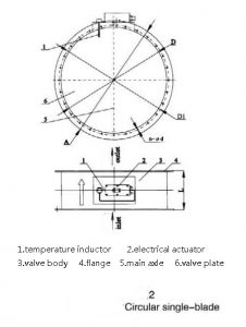
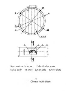
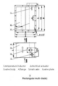
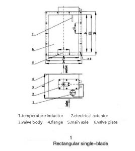
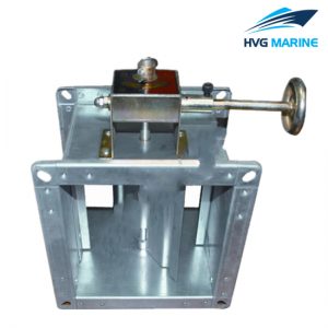
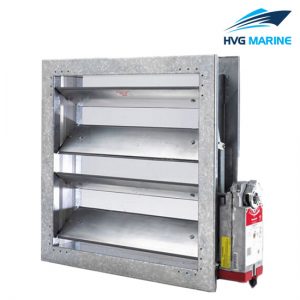
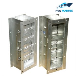
- Dampers are manufactured with single flap/multilouvers.The louvers are connected through suitable linkage to a controlling actuating device,such as electrical actuator/solenoid valve/pneumatic cylinder/fusible link.Louver/flap shaft are provided with bearings with greasing facility to enable smooth rotation.
- Louvers/flaps are made of mild steel,The louvers/flaps are designed in the form of a box and are sandwiched with high grade unsulating material which can withstand 9800 C for period of 90minutes,conform to CBRE/UL-555,Thereby acting as effective barrier in closed position to the flame path between air duct and fire effected area.
Features :
- 1.Control voltage:DC24V/AC110V/AC220V.
- 2.Protection degree:IP44/IP56/IP65/IP67.
- 3.Explpsion-proof degree:Exd||BT4~BT6 Exd||CT4~CT6.
- 4.Fusing temp is 70 ±3 °C,If the temperature of air within damper duct exceeds 70 ±3 °C or outside air temperature around duct near 95°C,The fusible of fire damper will be broken and cut off the control electrical power to close the fire damper.
- 5.Close Time:<10S.
- 6.Air leakage rate:<5m3/ m2 .h
- 7.On/Off signal output when the fire damper is open/close.
- 8.Each fire damper is supplied with one electrical control box to control on/off opreation of the fire damper locally or remotely.
Installation :
- 1.Shipyard should check the fire damper and ensure everything is OK before installation.
- 2.Fire damper should have a independent support to ensure the fuction of the fire damper.
- 3.A service space of at least 350mm should be reserved for maintanance.
- 4.Manhoule of at least 450x450mm is required when the fire damper is installed above ceiling or on duct.
- 5.No fire or welding are permitted with a scope of 3m from fire dampers,in order to ensure the remperature of sensor less than 65 °C.
- 6.Fire damper should be tested during installation,and be inspected regualarly after installation.
Process drawing :